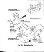
Engine Mounting
Rubber cushions support the engine and transmission at three points: at each side on the centerline of the engine and at the rear of the engine assembly between the transmission extension housing and the rear support crossmember.
Transmissions with an overdrive require a special mount and crossmember as seen in the scan.
ENGINE REMOVAL
Removal
The engine and transmission are removed as an assembly.
(1) Mark hinge locations at hood panel for alignment during installation. Remove hood assembly.
(2) Drain cooling system and crankcase.
(3) Disconnect heater and radiator hoses at engine.
(4) Remove battery.
(5) Disconnect automatic transmission oil cooler lines and cap (if equipped).
(6) Remove radiator assembly and fan shroud (if equipped).
(7) Remove radiator fan, spacer, and pulley.
(8) If equipped with air conditioning:
(a) Turn both service valves clockwise to the front seated position.
(b) Bleed refrigerant charge from compressor by slowly loosening service valve fittings.
(c) Disconnect and cap condenser and evaporator lines from compressor and cap compressor service valve outlets.
(d) Disconnect receiver outlet at disconnect coupling.
(e) Remove condenser and receiver assembly.
(9) Remove air cleaner assembly.
(10)Disconnect wires at the following components (if equipped).
- Starter motor
- Coil terminals
- Distributor
- Alternator
- AC compressor
- Temperature sending unit
- Oil pressure gauge sending unit
- Overdrive (disconnect at right rear of cylinder head)
- Solenoid vacuum valve
- Solenoid control switch (disconnect at right rear of cylinder head)
- Throttle stop solenoid
- Brake warning lamp switch
- Overdrive kickdown switch
(11)Disconnect the following lines (if equipped).
- Fuel line from tank at fuel pump
- Vacuum line for power brake unit at intake manifold
- Fuel return line at fuel filter
- Pressure vent line at carburetor
- Vacuum line for heater damper doors at intake manifold
- Vacuum line for fuel economy indicator switch
- Power steering pump (and plug at pump)
(12)Remove carburetor and seal intake manifold.
(13)Remove cylinder head cover.
(14)Remove vibration damper.
(15)Disconnect accelerator cable at accelerator control cable bracket.
(16)Raise and support car.
(17)Disconnect exhaust pipe at manifold.
(18)Disconnect transmission linkage and clutch linkage (if equipped).
(19)Disconnect speedometer cable at transmission.
(20)Remove propeller shaft and cap transmission output shaft.
(21)Support transmission with floor jack and remove rear crossmember.
(22)Attach lifting device and support engine assembly.
(23)Remove engine mount bracket-to-front support cushion attaching bolts.
(24)Lift engine slightly and remove front support cushions.
(25)Lower floor jack supporting transmission.
(26)Raise car with floor jack positioned under front crossmember until bottom of front bumper is approximately three feet from floor. Support car with jack stands.
WARNING: Be sure car is supported firmly.
(27)Remove oil filter and starter.
(28)Lifting at a point near the front of the cylinder head, partially remove engine assembly by pulling upward until rear of cylinder head clears cowl.
(29)Use floor jack to remove jack-stands and lower car.
(30)Remove engine assembly completely.
Installation
(1) Raise car with floor jack positioned under front crossmember until bottom of front bumper is approxi-mately three feet from floor. Support car with jack stands.
WARNING: Be sure car is supported firmly.
(2) Lower engine and transmission assembly slowly into engine compartment.
(3) Move lifting device back to center of cylinder head and support engine.
(4) Raise transmission into position with floor jack.
(5) Install rear crossmember
(6) Using lifting device to position engine, install front support cushions. Tighten support cushion-to-crossmember bolts to 30 foot-pounds torque and sup¬port cushion-to-engine mounting bracket bolts to 55 foot-pounds torque.
(7) Install transmission linkage and clutch linkage (if removed).
(8) Install speedometer cable.
(9) Install propeller shaft.
(10)Install exhaust pipe.
(11)Install oil filter and starter.
(12)Lower car.
(13)Install vibration damper.
(14)Install cylinder head cover.
(15)Install carburetor.
(16)Install accelerator cable.
(17)Connect all lines disconnected m Engine Removal (10).
(18)Connect all wires disconnected in Engine Removal step (9).
(19)Install air conditioning condenser and receiver assembly (if equipped) as follows:
(a) Connect receiver outlet to disconnect coupl¬ing.
(b) Connect condenser and evaporator lines to compressor.
(c) Purge compressor of air as outlined in Section 12B-Air Conditioning.
(20)CAUTION: Both service valves must be opened before the air conditioning system is operated.
(21)Install radiator fan, spacer, and pulley.
(22)Install radiator assembly and shroud (if removed).
(23)Connect automatic transmission oil cooler lines (if removed).
(24)Connect radiator and heater hoses.
(25)Fill cooling system, crankcase, and transmission to specified levels.
(26)Install and align hood assembly.
NOTE: Transmission throttle linkage must be adjusted after completing the engine installation.
