Repairing the Prestolite Igniton System
Changing the vacuum advance on your Prestolite Distributor. (Note: More images to be added at end.)
From 1974-1977 AMC/Jeep used a unique and much disliked Prestolite breakerless ignition system on their six and eight cylinder engines. The Prestolite system was only used a short while until AMC moved to the better Motorcraft Duraspark system, but it did perform adequately on a stock engine and should not just be torn out at the first sign of trouble if it had been performing adequately up until that point.
As with all electronic breakerless distributor systems, time, heat, and lack of maintenance can cause problems. You have to remember that these parts are now almost 40 years old and have tens of thousands of miles on them so you should expect that they will wear out from time to time.
Luckily the Prestolite system is very simple. It has one wire that is hot both during start and run to provide power to the whole thing; that’s the only connection to the rest of the wiring harness. This does mean that unlike the later Duraspark there is no crank retard in the system, but neither did the Points system nor the popular GM HEI have a crank retard.
The power wire connects directly to the coil and from there to the ignition control box. The major weak point in the whole ignition is this connector between the control box and the rest of the wiring. Corrosion can get in there and disrupt operation.
I recommend that even in a working system this connection be unplugged and cleaned before being reassembled with some dialectic grease.
The control box seems neither more nor less prone to failure then many first generation electronic ignitions, and exhibits the same symptoms the others do during failure. It behaves similar to a bad coil.
The control box is more susceptible to heat then later designs are and so it should be mounted in the coolest place possible, and it generally is from the factory. If you suspect that it or the coil is bad and you don’t know the history of the parts then go ahead and replace them as a set.
One of the notable things about the Prestolite system is that it does not use an external resistor like other systems, providing full current to the coil at all times. Another rare item is that it uses a hall-effect sensor to trigger rather the more common magnetic inductance system. This means it is less adaptable to aftermarket ignition control boxes.
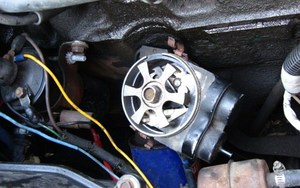
The strangest looking part of the whole system is the distributor. It has that odd-looking plastic vacuum unit on it. This unit is also a weak spot; the rubber diaphragm in it is thin and easily broken especially during an engine backfire.
While it may not be described in the manual, it is actually fairly easy to replace the vacuum advance module with the distributor in the car, and requires nothing more than a screwdriver, a 3/8 nut driver, and some sandpaper. If the unit has never been serviced then you may also need a pair of needle nose pliers and some patience.
;)
You begin by unplugging the control box, then remove the cap, rotor, and dust shield from the distributor body to expose the mechanism.
;)
Loosen the rubber grommet where the wires come through for the sensor and carefully work them out from around the spring on the advance unit so that they are free.
Using your nut driver, remove the small bolt holding the plastic advance to the distributor. Without trying to completely remove it, carefully loosen the advance unit minding both the sensor and the wiring. You may have to wiggle the reluctor wheel a bit or even turn the engine over slightly for alignment.
Once the unit is loose, position the screw holding the sensor to the advance unit where it is accessible. If you are unlucky it is a security bit and using your pliers and skill you will have to extract it then go find an exact match at the hardware store. If you are lucky it is a slotted screw and you can just carefully remove it with a magnetic screwdriver.
;)
The sensor is two small plastic parts and can now be carefully slid out of the groove on the vacuum advance unit and the whole piece carefully removed. Again be careful not to damage the wires.
Once the sensor is removed then the advance can be slid out. It may be difficult as you move over the spring pivot. You’re done. As the old manuals say, “installation is the reverse”.
;)
Before you install the parts check everything. Be sure the advance holds vacuum, everything is unbroken and the wiring not cut or nicked. Make sure both the retaining spring and the lever in the slot on the advance are there on the new unit.
If the old vacuum advance was difficult to remove a little bit of fine sandpaper on the slot it fits through can take the sharp edges and rough finish off and make installation easier. It doesn’t take much to make it slide right in, although it’s not a real precision fit as the vacuum advance can move left and right in the slot making lining up the retaining bolt difficult.
Once the vacuum unit is fitted, but before you attach it, it is time to fit the sensor. Slide it into the slot on the side and install the screw, remembering that it is in plastic and should not be too tight, just snug. Then back off the screw just a bit so you can move the sensor around.
Place the retaining spring on the sensor to hold it down and route the wires correctly around the spring pivot to the other side of the distributor. You may need to work with the spring and the wires to get them to not interfere with each other or the reluctor wheel.
;)
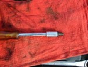
Now using the reluctor wheel and some patience, align the sensor so it will fit evenly in the gap of the reluctor, then snug down the screw. You may need a small screwdriver, a piece of welding rod, or a paperclip to find the hole for the attaching bolt and align the vacuum unit. Once aligned install the attaching bolt and put the remainder of the distributor together.
Test fire the engine and check the timing.
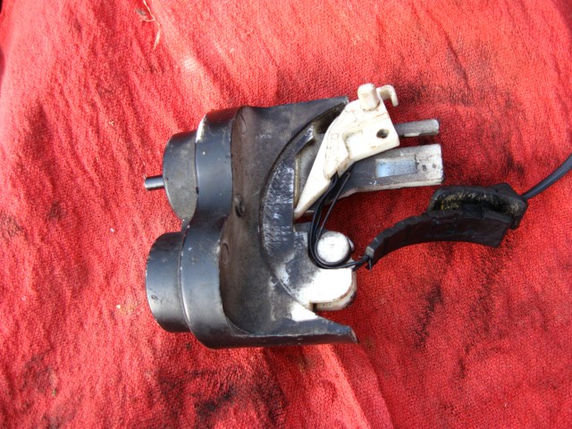
Now, for a little autopsy on the vacuum advance unit.
Deceivingly, the unit appears to have two diaphragms, but in reality there is only one. A lever rides between the pin from the vacuum diaphragm and a dummy pin on the opposite side. The length of this pin may determine the range of available advance with a longer pin granting more range.
I would be interested to see examples where the second diaphragm was used. During the 70s there were many strange modifications designed to control emissions, and many of those changed how vacuum advance was applied to the distributor. Generally they reduced or eliminated vacuum advance to ward off NOX emissions, while sometimes they applied manifold vacuum while cold or hot. The second dummy diaphragm may have just been a placeholder for future emissions use.
The plastic unit is in two parts held together by two rivets in the middle and is easily separated. You can see on this one from the discoloration where the diaphragm ruptured.
Beneath the diaphragm are a spring and a washer that control how quickly the vacuum advance occurs.
On the advance unit there is a slot in which the sensor rides, and this slot may also be a limiting factor as to the range of available advance. Vacuum advance is achieved by moving the sensor while rpm advance is achieved my moving the reluctor wheel, so the two are achieved independently.
 Ignition